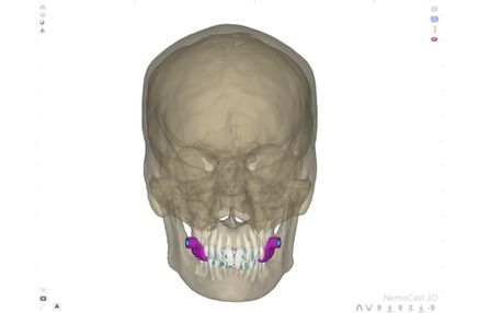
Microscrews in orthodontics have been in clinical practice for over two decades. The concept isn’t new: a small-diameter titanium device that provides temporary skeletal anchorage to move teeth that, without it, couldn’t be moved with predictability.
What has changed is the level of precision required in today’s cases, as well as the real possibility of planning microscrew positioning with millimetric precision before the patient is seated in the chair.
In this article, we’ll explain how we approach the digital planning of skeletal anchorage microscrews, what clinical information CBCT adds compared with conventional radiography, what the evidence says about the accuracy of insertion guides, and when it makes sense to outsource guide design to our team.
What Skeletal Anchorage Makes Possible That Wasn’t Possible Before
Conventional anchorage relies on the teeth. Microscrews eliminate this: the bone serves as the anchor, not the brace, and this opens up a wide range of movements that previously required patient cooperation (using extraoral brace systems) or were simply not biomechanically feasible.
Absolute Anchorage for Incisor Retraction Without Lossing Posterior Anchorage
In extraction cases involving severe crowding or biprotrusion, incisor retraction is only efficient if posterior anchorage remains stable. With conventional mechanics, that anchorage is compromised: the molars move mesially even when this movement is not desired.
With palatal or buccal microscrews, anchorage is independent of the posterior teeth. The incisors can be retracted without the molars moving in the opposite direction.
Molar Intrusion and Gummy Smile Correction
Molar intrusion is one of the hardest movements to control with conventional appliances. Microscrews allow direct vertical force to be applied to the molars from skeletal anchorage, making it possible to correct anterior open bites and reduce gingival exposure in gummy smile cases without surgery.
Microscrew-Assisted Palatal Expansion (MARPE)
Conventional expanders act on the molars. In adults with a more rigid or already fused midpalatal suture, this tooth-borne force does not produce true skeletal expansion.
Miniscrew-assisted rapid palatal expansion (MARPE) appliances transfer force directly to the palatal bone, making transverse expansion possible in adults who previously required orthopedic surgery.
Distalization Without Extraoral Appliances
Unilateral or bilateral molar distalization with microscrews in the anterior palate avoids extraoral headgear and doesn’t depend on patient cooperation. Control of the force vector and the point of application determines whether distalization occurs without associated molar extrusion.
Why Positioning Is the Critical Factor With Microscrews
Microscrew insertion seems simple. Access is minimal, the procedure is quick, and recovery is immediate. However, the exact insertion site determines whether the device will be functional, stable, and safe.
The insertion angle determines the entire mechanics of the case. An angular deviation of just a few degrees from the plan can change the force vector on the target tooth, compromise parallelism when there are two or more microscrews, or shorten the lever arm when using a rigid device such as a MARPE.
Bone density and cortical thickness are variables that aren’t visible on a panoramic radiograph. The anterior paramedian palatal area is the safest insertion zone because it provides two cortical layers, no sensitive structures, and a lower vascular risk. But even within that zone, bone thickness varies. A bicortical insertion planned without prior 3D imaging turns something manageable into an uncontrollable variable.
Root proximity changes with each phase of treatment. In treatments where the teeth have already moved, the relationship between the roots and the insertion site differs from what the initial image showed. Without integrating the updated CBCT into the insertion plan, this variability cannot be controlled.
What CBCT Reveals That Conventional Radiography Doesn’t Show
Panoramic radiography provides an image projected onto a single plane. It is useful for many purposes but insufficient for planning the position of a microscrew with precision.
CBCT adds three layers of information that radiography can’t offer:
- Actual bone thickness at the insertion point. The value in millimeters along the exact bucco-palatal or vestibulo-lingual axis where the screw will enter—not an estimate based on a projected image.
- Three-dimensional relationship with adjacent roots. Which root is closest, at what exact distance, and in which direction. This is what allows the insertion angle to be designed without relying on intraoperative visual references.
- Cortical quality. Not all cortical bone has the same density. An area with thin or low-density cortical bone can affect the insertion protocol or rule out the initially planned site.
In palatal bicortical insertion (the usual approach in the anterior palate), two cortical layers must be crossed. Without CBCT, the screw length needed and the safe angle are estimates. With CBCT, they’re data.
How We Plan Microscrew Position With NemoCast
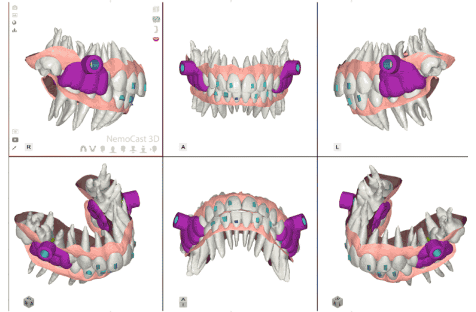
NemoCast integrates CBCT, STL arch models, and the patient’s photographic record into a single work environment. From there, we plan the position of skeletal anchorage microscrews and design the insertion guide.
Integration of CBCT, STL Models, and Photographs in a 3D Environment
The starting point is the superimposition of the three data sources: the CBCT bone volume, the digital arch models, and the clinical photographs. NemoCast automatically segments the teeth in the CBCT using artificial intelligence, which reduces case preparation time and increases the accuracy of reference points.
Analysis of the digital models is completed in just a few minutes. From this foundation, we build the microscrew plan with the real relationship between roots, alveolar bone, and adjacent structures visible in all three planes of space.
Visualization of Roots, Alveolar Bone, and Critical Structures
With the CBCT integrated into the plan, we can visualize the following in real time:
- The position and morphology of each root at the planned insertion point
- Palatal or buccal bone thickness on the exact insertion axis
- Cortical density in the selected area
- The screw’s trajectory in all three planes before performing any procedure
- We can select the required microscrew length based on bone thickness, avoiding approximate measurements and choosing the correct size from the outset.
This allows the angle, microscrew length, and exact insertion site to be adjusted before the patient reaches the chair—not during the procedure.
Insertion Guide Design and Manufacturing
Once the position is defined, we design the insertion guide directly in NemoCast. The guide transfers the planned entry point and angle to the oral environment with millimetric precision, eliminating the need for intraoperative visual estimation.
NemoCast allows the guide to be manufactured in the clinic itself with any 3D printer compatible with biocompatible resins for intraoral use, or the manufacturing can be outsourced. In both cases, the guide’s STL file comes directly from the digital plan.
3D Insertion Guide vs. Freehand Placement: What the Evidence Says
The relevant question isn’t whether microscrews work: that’s been established for years. The question is what difference the 3D guide makes compared to freehand placement in terms of positioning accuracy.
Angular error: Pozzan et al. (2022, Progress in Orthodontics) quantified the accuracy of digital guides in palatal insertion. They found a mean angular error of 2.12° ± 1.62 in the laboratory step (printing and guide fitting) and 6.23° ± 3.75 in the clinical step (insertion with the guide in the mouth). The final error comes mainly from the clinical step, not from the printed guide. The guide reduces variability; clinical execution still introduces deviation.
Linear deviation: Al-Gazzawi et al. (2024) documented a mean horizontal linear deviation of 0.32 ± 0.15 mm in digitally guided insertions in the anterior palate, within the clinically acceptable range for most cases.
What this means in practice:
- In cases with 2 microscrews and devices with some flexibility (such as elastics or orthodontic archwires), a single-visit protocol is viable with a digital guide. The error of a few degrees is compensated for during activation.
- In cases with 3 or more microscrews or very rigid devices (MARPE, 4-point implant-supported expanders), parallelism between insertions is critical. Accumulated angular error can affect the appliance’s fit, and a two-visit protocol is recommended.
- In palatal bicortical insertion, two cortical layers must be crossed and depth controlled precisely. Without 3D planning, there is less margin when estimating the required screw length, and the risk of error increases.
The guide is necessary. What makes it useful is the prior planning that resolves the case before it’s manufactured.
When to Outsource Microscrew Guide Design
Not every microscrew case justifies the internal planning time. And not every clinic has the digital workflow set up to produce insertion guides in-house.
From our planning center, we offer microscrew guide design and manufacturing as a service:
The specialist receives the case with the positioning plan and the designed guide, reviews it in the web viewer, requests adjustments if needed, and approves it before setting the insertion date.
It makes particular sense to outsource in three situations:
- High-complexity cases: bicortical insertion, 3 or more microscrews, MARPE in adults with a fused or irregularly shaped palatal suture.
- First cases with a digital workflow: clinics that are incorporating microscrew planning and want to validate their first designs before producing them independently.
- High volume: when internal planning time isn’t compatible with the specialist’s schedule.
Frequently Asked Questions About Microscrews and Digital Planning
What Records Do I Need to Plan a Microscrew’s Position With NemoCast?
The minimum records are intraoral photographs and digital arch models in occlusion in STL format. For insertion guide design, CBCT in DICOM format is essential: without it, three-dimensional visualization of roots, cortical bone, and adjacent structures isn’t possible. If treatment has already started, it is recommended that the CBCT scan be obtained with the teeth in their current positions to capture the actual situation at the time of insertion.
Can I Manufacture the Insertion Guide in My Own Clinic?
Yes. NemoCast generates the guide’s STL file directly from the digital plan. That file is compatible with any dental 3D printer and any biocompatible resin approved for intraoral use. If you prefer not to manufacture it in-house, our planning center offers physical manufacturing or the delivery of print-ready STL files.
In Which Cases Is It Especially Important to Use a Digital Guide for Microscrews?
In palatal bicortical insertion, where depth must be controlled precisely and two cortical layers crossed. In cases with 3 or more microscrews, where parallelism between devices affects the appliance’s function. In patients with limited bone anatomy or roots close to the planned insertion site. And in treatments with rigid devices such as MARPE or implant-supported expanders, where accumulated angular error can prevent the appliance from seating properly.
How Long Does a Skeletal Anchorage Microscrew Stay in the Mouth?
The microscrew stays in place for as long as its assigned anchorage function is needed: from just a few months in distalization mechanics to the entire active phase in MARPE treatments. Once its function is complete, the device is removed in a procedure that takes only a few minutes and, in most cases, doesn’t require general anesthesia or sutures.
Do you have a microscrew case that you want to plan with precision? Our team designs the insertion guide in just a few days. Contact our team.